mobile separation unit for well exploration
The basic principle embedded in the installation's operation scheme is that the downhole fluid entering the process equipment unit is divided into its component components and each component is subsequently measured separately (gas flow is measured separately, liquid flow is measured separately).
This scheme of the installation allows you to more accurately measure the flow rate of the well and each component individually without using expensive equipment to measure multicomponent media, calculate the condensate factor and take samples of each component individually.
The developed equipment is based on a mobile platform and provides the ability to determine the main technological parameters of the well operation.
The mobile chassis for the PSU is selected taking into account the need for high cross-country terrain and climatic design, corresponding to the ambient temperature conditions in the borehole research area.
The mobile chassis provides the placement of technological equipment on the transported trailer in the amount of 1 pc. The trailer chassis provides sufficient load capacity and cross-country capability.
On the chassis of the tractor vehicle there is a thermal box unit for the regions of the Far North with the possibility of autonomous heating. The block box has 2 compartments with separate entrance doors to each compartment. One compartment is "technological", with an area of at least 1/3 of the area of the control box, for accommodating automation cabinets and equipment control panels, the second compartment is for household use, which houses the operator's automated control system and personnel sleeping places in the amount of at least 2.
When preparing the installation for operation, the trailer chassis with technological equipment is located directly on the well and is connected to the manifolds of the fountain fittings of the well under study, the chassis of the operator module is located at a safe distance from the well (at least 100 meters) beyond the boundaries of the explosive zone and the zone of possible gas contamination. Sensors, instruments, and power drives are connected via multi-wire power and signal cables. The signal cables are marked intrinsically safe circuit.
The control and operation of the installation is carried out by the operator from the operator's ARM located on the chassis of the operator module. Control cabinets with controllers of the automated process control system and power cabinets are located in a separate compartment of the operator module behind a sealed partition.
In order to reduce the range of sensors used, installed on technological equipment, the operating pressure and temperature signals are selected from the control system of flowmeters.
The PSU installation performs the following main functions:
- determination of the well flow rate for gas and liquid (main function)
- determination of the working pressure of the well
- determination of the amount of liquid in the gas (the amount of liquid is defined as the total content of a mixture of hydrocarbons and water, the installation is not designed to separate and account for individual components of the liquid flow from the well, such as gas condensate, water, etc. For these purposes, auxiliary equipment is used, which is not included in the delivery package)
- determination of the temperature of gas and liquid flows
- determination of incoming flow density
- sampling of the gas-liquid mixture at the entrance to the installation
- sampling of gas and liquid at the outlet of the installation
- measurement, recording and transmission of data on the progress of the study in the automated process control system of the facility.
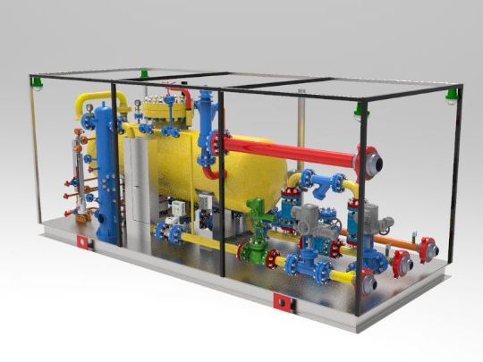
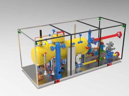
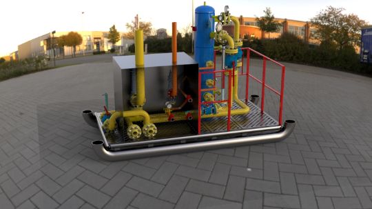
The installation is a complex of separation equipment having 2 separation stages in its harness, with shut-off and measuring fittings, mounted measuring equipment mounted on a frame and mounted on a trailer chassis.
The frame design allows the installation to be used both in a stationary (long-term) position and in mobile versions on the trailer chassis.
The scope of delivery of the installation includes the required number of pipelines with BRS nuts for connecting the control unit to the fountain fittings at the well. The length of the pipelines and the number of hinges are determined by the customer and indicated in the general view drawing and working design documentation.
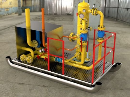
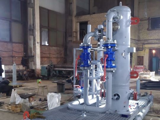
The installation allows you to measure the flow rate of gas condensate wells, measure the density of the borehole fluid, separate the borehole fluid into its components (gas-liquid), and sample the separated liquid and gas at the inlet and outlet of the installation into standard samplers.
To automate the well exploration process, the installation is equipped with valves with electric actuators, level sensors, flow meters on the purified gas and liquid drainage lines, pressure and temperature sensors, and an safety valve.
The installation automation system (ACS) is made in the form of a single software and hardware complex based on a programmable controller, and is a system that includes:
- sensors for obtaining information about the progress of the technological process installed directly on the equipment,
- electric actuators installed in the harness of the control unit,
- Operator's automated control system, which allows remote control of the technological process of well exploration,
- a source of autonomous power supply with the capacity necessary for the normal operation of the ACS control cabinet and actuators.
The installation also has the ability to connect to the automated process control system of the facility in order to transfer the main parameters of the operation of the well under study to the automated control system of the field operator. The data transfer protocol is agreed separately at the development stage of the ACS installation and agreed with the Customer.
Sampling pipes are provided for liquid and gas sampling at the inlet and outlet of the installation, as well as on the drain line.
To prevent hydrate formation, hydrate inhibitor supply pipes are provided at the inlet and outlet of the installation.