About us
Our activities:
Smart Control is a technology company that owns a number of modern developments and know-how in the field of gas industry, food technologies and energy-saving technologies.
Extensive experience in the market and a team of highly qualified specialists allow us to implement the most complex projects with the best results in a short time
The company carries out developments in the area of its competence, which allows us to constantly improve the offered technologies and be at the top of technological development, offering Customers only the latest developments. We have received more than 40 patents for our developments.
We have designed and implemented more than 50 modern technological complexes. We are constantly improving and developing our developments to offer you the best technical solutions in the area of our competence.
Over 20 years of experience in the industry
wide geography of works and services
Qualified specialists to solve any non-standard tasks
Our areas of specialization
Our competencies extend to:
Our areas of specialization
Our competencies extend to:
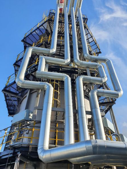
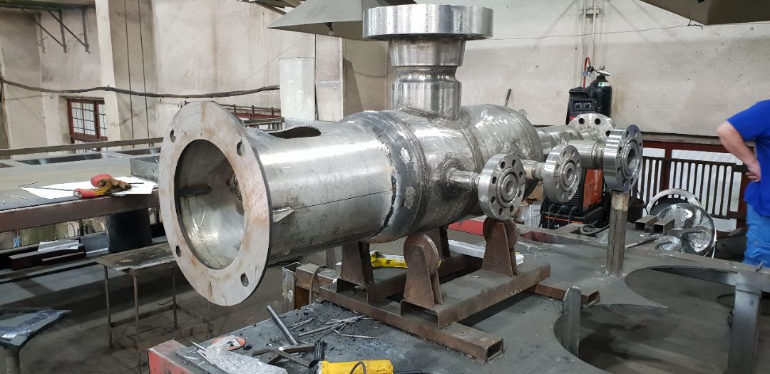
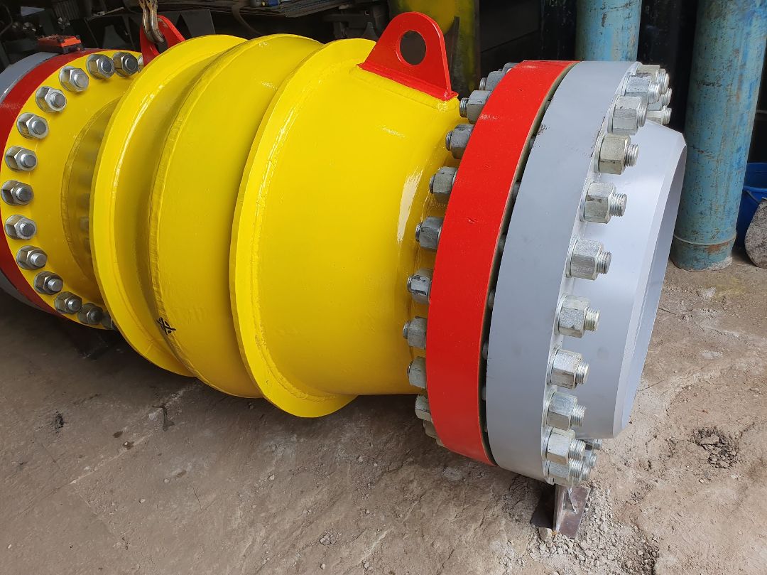
Gas cleaning equipment. Gas separators SGV-7
Gas separators are designed to clean the gas flow from liquid droplets and mechanical impurities. The SGV-7 gas separators we produce have the smallest overall dimensions with high operating efficiency. SGV-7 separators have proven themselves as reliable and efficient equipment designed for cleaning gas flow at gas infrastructure facilities. Liquid carryover from SGV-7 gas separators is from 4 to 15 mg/Nm3. The equipment has positive reviews and is protected by invention patents.
All separation equipment we produce can be manufactured in a block design with high factory readiness, which in turn reduces the time required to install the equipment at the facility and the time it takes to start up.
In addition, block installations can be equipped with local automation systems, which can be integrated into the automation system of the facility where the installations are installed.
Filter-separators SGV-7F with coalescer cartridges
The equipment has received positive reviews and is protected by invention patents.
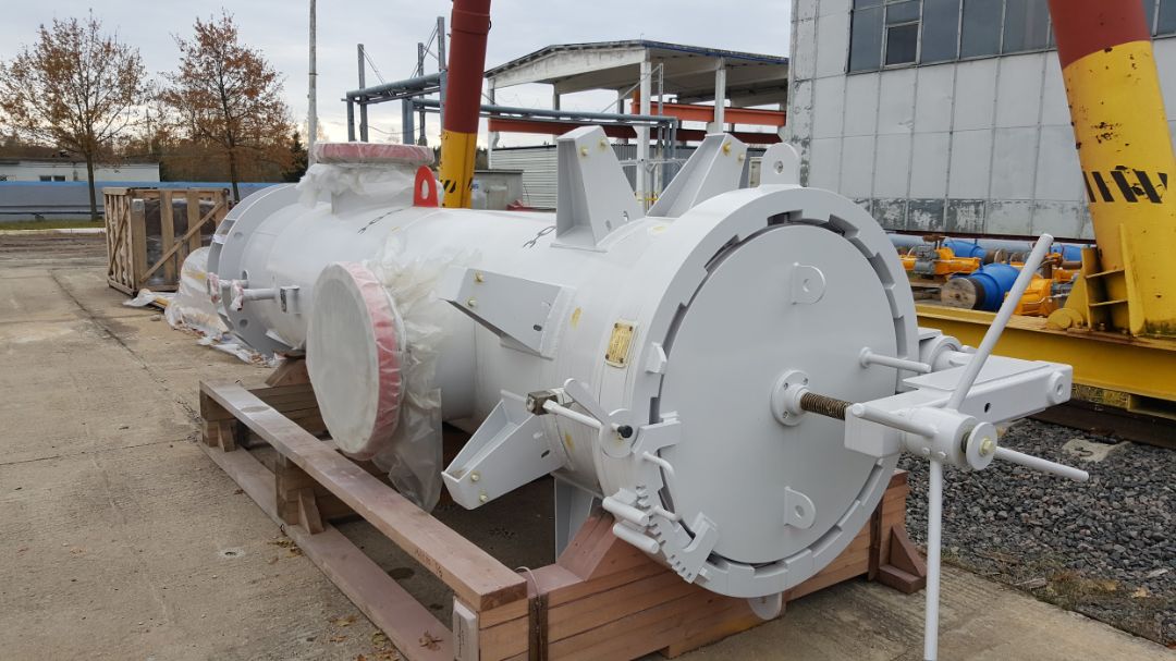
Horizontal dry gas filters
The horizontal filters separators we produce have increased efficiency compared to existing models due to the optimal arrangement of internal filter elements, which allows not only to ensure a higher quality process of filtering dry gas from mechanical impurities, but also allows for filter-separators to be serviced in a shorter time frame, which reduces downtime.
The use of modern filter cartridges, including duplex type, allows for the most efficient gas purification from mechanical impurities.
The filter cartridges we use have the lowest resistance and increased dust capacity, which allows for less frequent cartridge replacement, which improves the economic performance of the equipment.
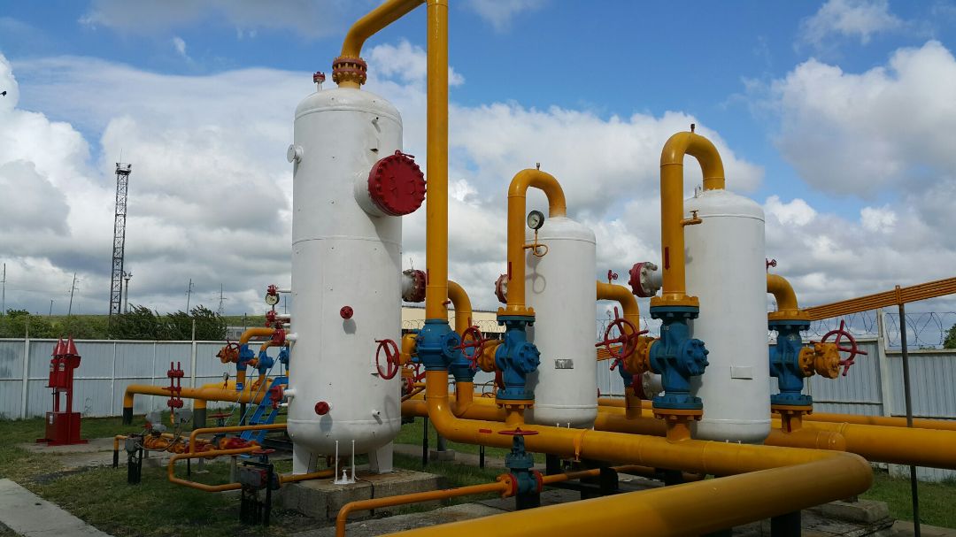
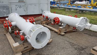
Block separation units
Block separation units designed to purify natural gas and associated petroleum gas have a high degree of factory readiness, which ensures simplified installation at the installation site and shortened commissioning times at the facility.
Block separation units have all the necessary strapping in their design, including automation devices and actuators such as shut-off valves, taps, valves, safety valves, and others necessary for the normal operation of the unit and the performance of basic functions for the intended purpose of the equipment.
Block separation units based on SGV-7 gas separators have not only high-quality gas purification with minimal pressure drop, but also low overall and mass characteristics compared to their counterparts, which allows them to be transported by the main types of land and rail transport.
The block type of installations allows you to significantly reduce the installation time on site due to the factory readiness of the unit. At the same time, the automation system of the installation is easily integrated into the automated process control system of the facility under construction.
Operation gas desiccant filters
Pneumatic actuators powered by operation gas are used as the main actuators on valve spots of main gas pipelines.
Pre-purified and dried natural gas is used as a operation gas, which is transported through main gas pipelines.
The harsh climatic conditions of operation of main gas pipelines imply high-quality purification of operation gas to prevent failure of the actuators to ensure their reliable operation throughout their entire service life. Operation gas drying is required to prevent the pistons of the pneumatic actuators from freezing over.
We have developed operation gas filter dryers that solve both of these problems in one device.
The desiccant filters we produce have a simple and reliable design that ensures reliable operation of the actuators of the crane platforms of the main gas pipelines throughout the warranty period.
Well testing equipment
The mobile well survey units we manufacture allow us to conduct gas-dynamic surveys on wells that have been completed by drilling, obtaining all the main parameters of the well’s operation.
Placing the process equipment on a mobile chassis gives the equipment mobility, which allows well surveys to be carried out in a shorter time frame without wasting time and resources on the process of installing equipment in the wells. The automation system of the installation allows recording all the main parameters in an automated mode with recording the research results in a well report
modernization of obsolete separation equipment
The specialists of our company have developed a program, methodology and design of the SGV-7 separator, which are used in the reconstruction and modernization of morally and technically obsolete separation equipment.
The essence of the proposal is that using the body of the existing separator, its inoperative internal elements are replaced with the built-in separator SGV-7. Having identical technical characteristics, the separator SGV-7 compares favorably (by an order of magnitude) with the installed gas separators in terms of dimensions and gas flow cleaning efficiency.
Thus, using only the separator body, which is subject to re-examination, as a result of reconstruction and modernization, with the least material costs, it is possible to obtain equipment with a cleaning efficiency of up to 99.99% and the removal of droplet moisture up to 4 mg/m3.
During reconstruction and removal of the internal elements of the separator, structural elements remain, to which the built-in separator is subsequently attached using welded joints. Welding work carried out during equipment reconstruction does not affect the body elements of the reconstructed separator and, as a result, flaw detection tests of these joints are not required.
The dimensions of the SGV-7 separator and the fasteners required to secure it in the separator body allow them to be delivered inside the reconstructed separator through the existing manholes.
A full reconstruction of the device is carried out by a team of four specialists within five days. After the reconstruction, the separator continues to operate in the normal mode with increased efficiency.
Equipment set for determining the efficiency of separators
Studies of the efficiency of the separator are carried out in accordance with the Program and methodology for conducting tests to determine the efficiency of the gas separator.
The method is based on measuring the volumetric flow rate of gas and sampling a portion of the flow being studied while maintaining the speed, temperature and pressure, and then separating it on a coalescing material with a previously known efficiency, measuring the amount of gas passing through this material and the captured liquid. Under these measurement conditions, it is possible to analyze the selected flow using a test filter separator. In this case, the separation of the flow under study and measurement of the amount of separated liquid occurs without changing the thermodynamic conditions of the technological process under conditions of isokinetic selection process.
During the work, measurements are taken of the separator's efficiency before and after repair work. In both cases, measurements are taken in samplers installed on the inlet and outlet pipes of the separator.
Vortex tube for use at gas distribution stations as a gas heater and in integrated gas treatment plants for gas cooling
The main effect of the vortex tube is the division of the gas flow into 2 flows with different temperatures, different from the temperature of the original flow, a hot flow and a cold flow.
Thus, this allows the use of a vortex tube in various elements of the gas preparation process flow chart, as a throttle (with a higher effect compared to the Joule-Thompson effect), as a gas heater.
The difference in flow temperature compared to the initial temperature can reach 60 degrees Celsius. In addition, the temperature difference depends on the pressure difference on the vortex tube (the pressure difference between the inlet flow and the cold/hot) and the difference in performance between the inlet and the cold/hot flow.
We have designed, manufactured and tested vortex tubes for compressed air and natural gas. During the tests, we were able not only to confirm the operability of the vortex tube itself as a device in general, but also to obtain statistical results on the tube's operating time in various modes.
At present, we have developed designs and standard sizes of vortex tubes for installation at gas industry facilities (gas distribution stations, gas treatment plants, compressor stations) that allow obtaining a cooled or heated gas flow, provided that there is a pressure drop across the vortex tube.
Moisture and oil separator with compressed air drying function for pneumatic systems
The SGV-7F moisture and oil separator is designed to clean and dry compressed air and prepare it for the requirements of actuators in order to increase service life and prevent moisture ingress.
The moisture separator design consists of 3 stages of compressed air cleaning and preparation.
A vortex separator is installed at the first stage, where the main separation of droplet liquid from the compressed air flow occurs. This ensures a decrease in moisture ingress to the second and third stages, which results in an increase in the service life of the device.
The second stage is equipped with a cartridge with an internal filling of silica gel, which ensures high-quality drying of pre-cleaned air to the parameters required by operating conditions, including in the Far North.
At the third stage of purification, a filter is installed, which ensures the filtration of compressed air from mechanical impurities and traces of silica gel decomposition. This ensures the purification and drying of compressed air.
Today, similar types of equipment are known: moisture separator, dehumidifier, filter, but as separate types of process equipment, the assembly in a single housing is not supplied
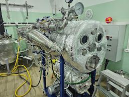
Steam recovery plant
The main purpose of the steam recovery unit is to condense the steam emissions from the boiler in order to prevent the spread of steam emissions into the atmosphere and to prevent the spread of odor contained in the steam fraction of the boiler output.
The unit operates on the principle of condensing steam into a liquid state, converting the steam fractions formed during boiler operation from the aggregate state of “gas” to the aggregate state of “liquid”.
The equipment set of the unit includes the following basic design elements:- gas-liquid separator at the unit inlet. It is designed to clean the steam entering the unit from liquid droplets and finely dispersed fractions in order to remove them and prevent them from entering subsequent condensation stages. This increases the efficiency of condensation. The separated liquid from the separator is discharged into the storage tank through the liquid discharge line.
- the first stage of condensation. It is the first stage of reducing the temperature of the steam, where the primary cooling of the steam occurs with condensation of the liquid and drainage into the storage tank.
- the second stage of condensation. It is a two-stage refrigerator-condenser, designed for complete cooling of the incoming steam to the temperature of the refrigerant, which leads to further development of the process of condensation of steam and the components contained in it.
The condensed liquid with the contained components is drained through the liquid discharge pipes into the storage tank.
- the storage tank is designed for an accumulation volume of 0.4 m3 and is intended to accumulate condensed liquid during the operation of the unit. The storage tank is equipped with a level measuring column designed to control the liquid level in the tank and a ball valve on the drain line for periodic discharge of liquid into a separate tank for subsequent processing or disposal.
- refrigerant supply manifold. Designed to supply and distribute refrigerant between the first and second stage refrigerators - condensers in such a way as to ensure the optimum refrigerant temperature in the condenser with the minimum possible refrigerant consumption
Equipment for obtaining vacuum extracts of plants
The equipment and technology we develop allow us to obtain extracts from plant materials at low temperatures under vacuum. The use of vacuum during extraction allows to significantly reduce the temperature of the technological process (to +34-36 degrees Celsius), which allows to preserve all useful substances (vitamins, proteins, complex compounds) in the extract and prevent their thermal destruction and degradation.
The resulting extracts not only have an increased content of useful substances in the final product, but also retain all the beneficial properties of the original raw materials unchanged. The increased concentration of useful ingredients allows the use of extracts both for personal use and for further processing as raw materials in the production of medicines and dietary supplements.
Equipment for the technological process of wine dealcoholization
The process of de-alcoholization of wine involves the process of distillation of wine material in order to remove alcohol. During the distillation process under a deep vacuum, the wine material boils at temperatures of 24-25 degrees Celsius, which does not have a detrimental effect on the original raw materials, allowing the organoleptic properties of the original wine to be preserved while maintaining the bouquet of aromas and taste.
The developed technology and set of equipment allow not only to produce non-alcoholic wine, but also to obtain an alcoholic distillate of wine spirits, which are used in winemaking to stop the fermentation process.
The equipment set and technology are protected by a patent for invention and allow the technological process to be carried out with any quality of wine material.
The technology and equipment can be adapted to the customer’s needs, taking into account the customer’s existing traditions and winemaking technology.
Heat pumps.
Equipment for obtaining hot water from split systems
Unit of hot water production systems
The equipment developed and patented by us allows you to get hot water absolutely free of charge, provided that you use split systems for air cooling.
The set of equipment allows its use both in domestic and industrial premises.
At the same time, the only condition for receiving free hot water is the use of a split system. In other words, when you turn on the split system, you can always count on free hot water in any required volume.
The resulting hot water can be used both for hygienic purposes, for example in the summer, and for heating the underfloor heating system, for example in the cold season. The amount of warm water obtained (with a temperature of up to 80 degrees Celsius) is limited only by the volume of the storage tank and the power of the split system used.
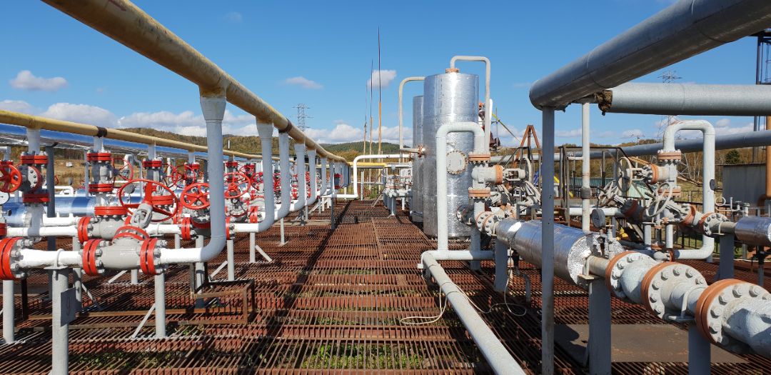
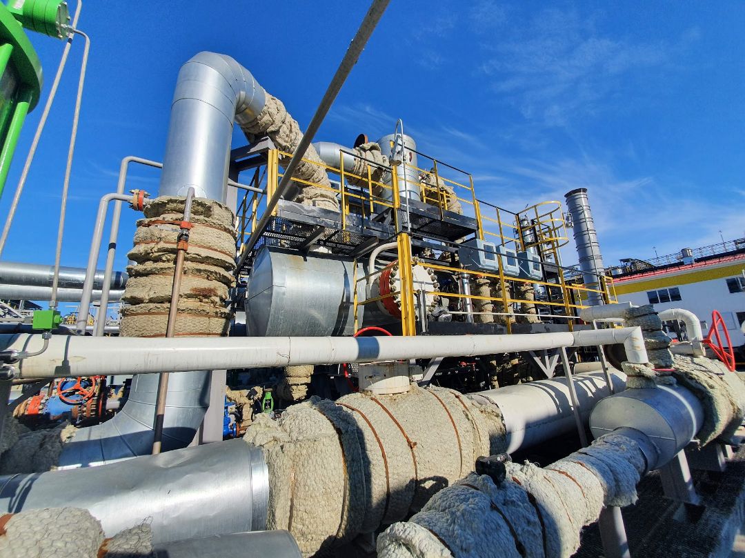
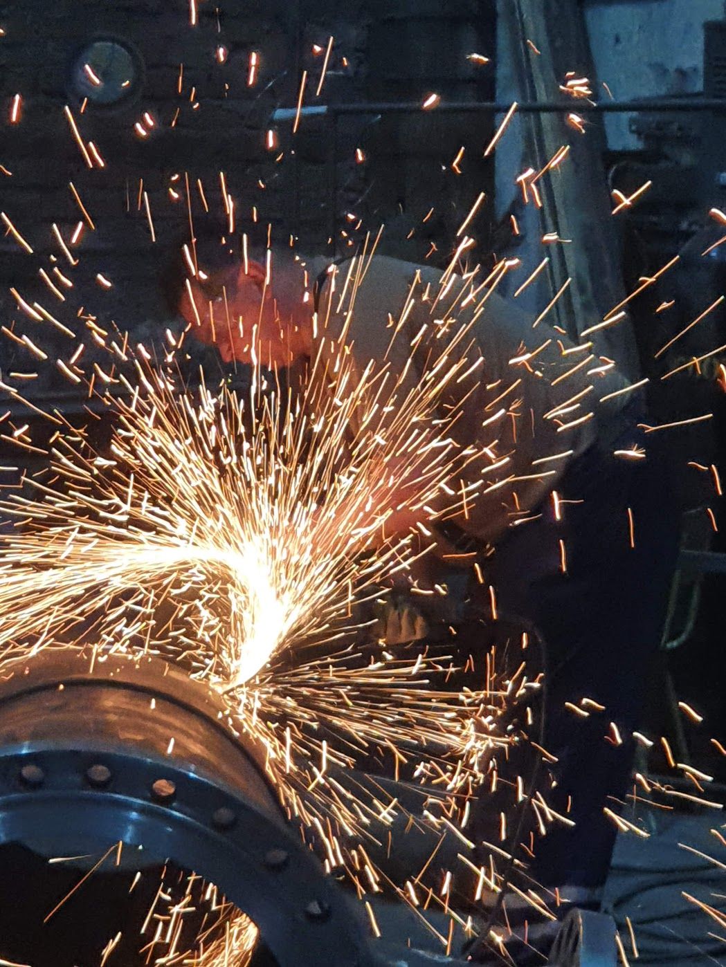
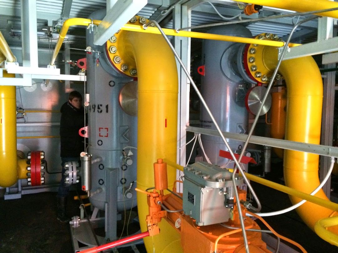
gallery
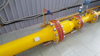
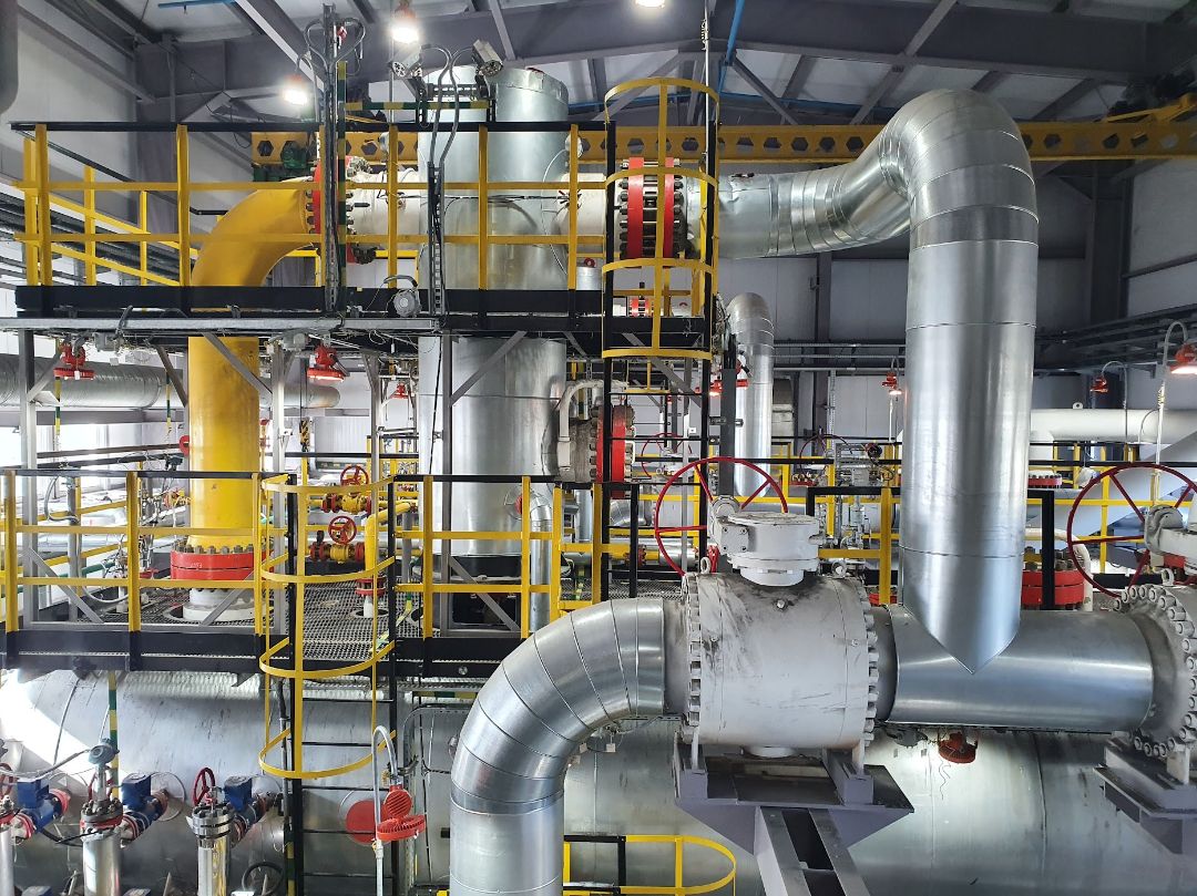
finished projects:
gallery
finished projects:
All products we manufacture are patented and have the necessary permits
patents and certificates
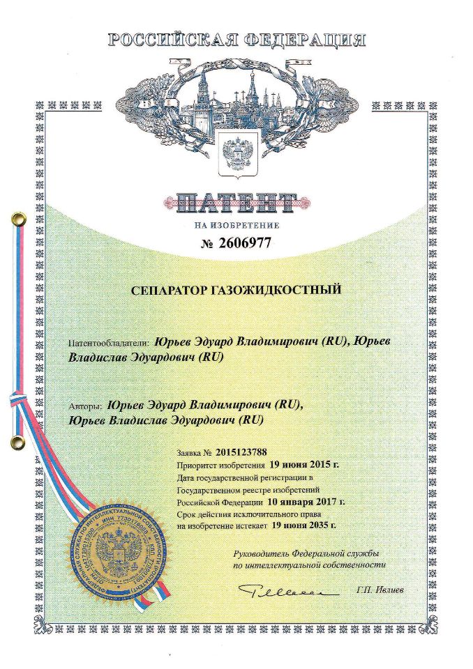
Патент на газовый сепаратор СГВ-7
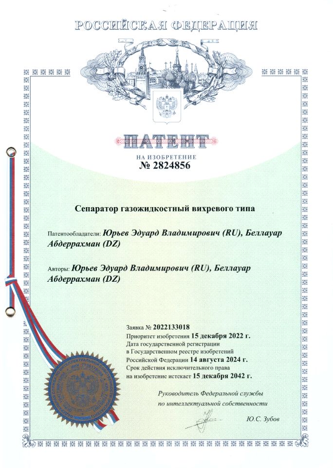
Патент на сепаратор СГВ-7
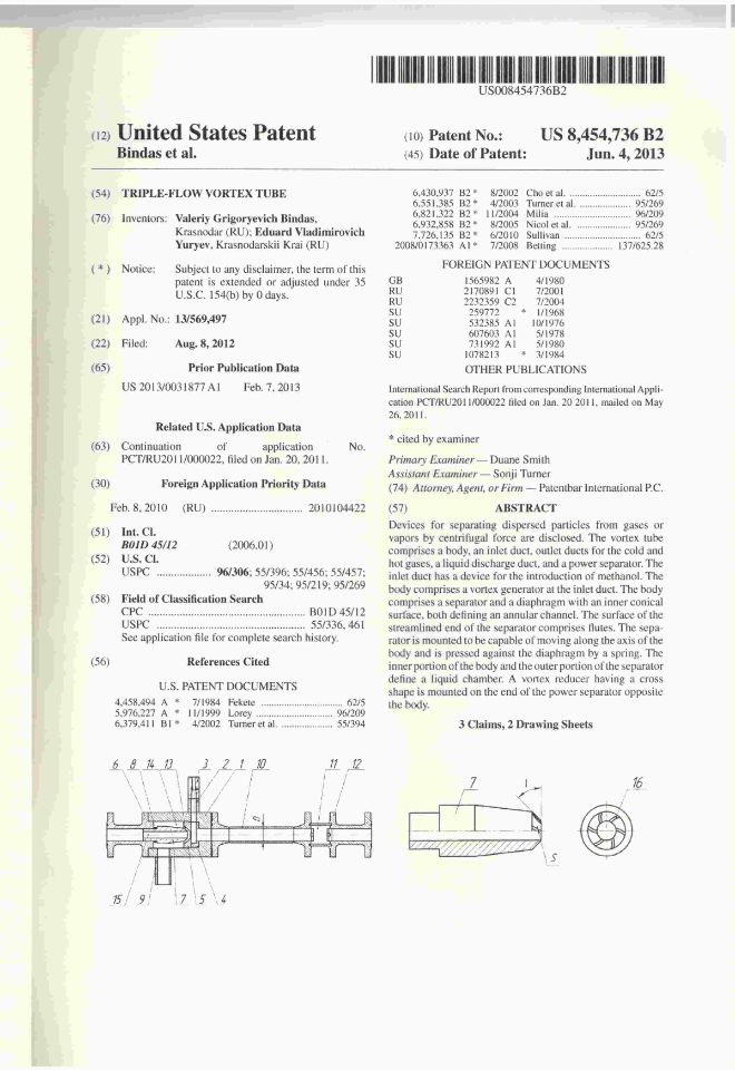
Патент США
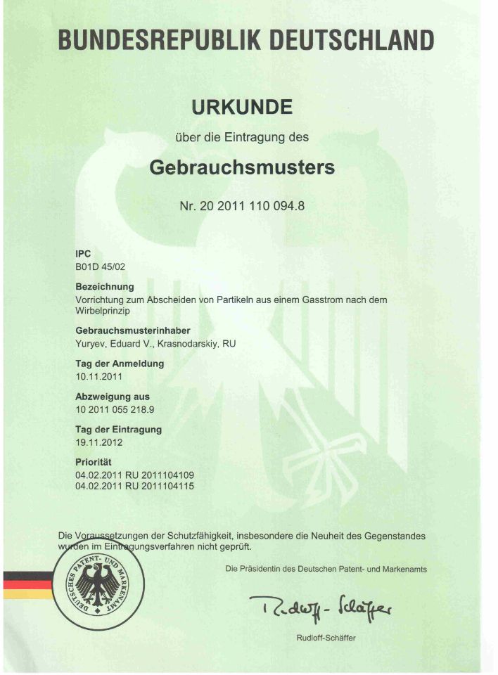
Патент Германии
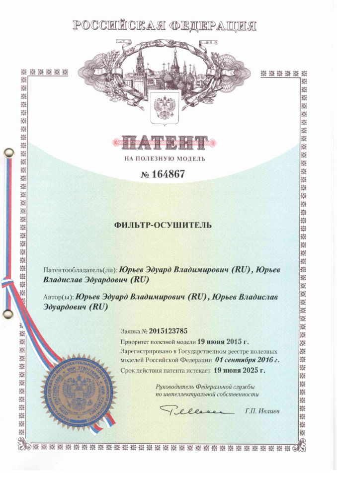
фильтр осушитель
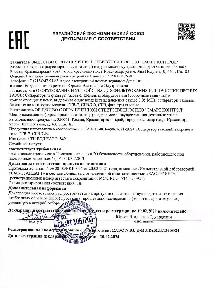
Декларация соответствия
Патент на безалкогольное вино
Патент на изобретение
Патент на изобретение
Feedback
This is what they tell about us:
Отзывы
Вот, что говорят он нас:

Николай газпромович
Быстро чертят чертежи, быстро изготавливают. В ответ на опросный лист подготовили чертеж общего вида бесплатно.
Доволен полностью.

Лукойл нефтекачаев
Оборудование отгрузили быстро. Работает на бизнеса.
Респект.

скважина новатековна
Ответили быстро, изготовили именно то, что было нужно.
Оборудование работает как было описано в техническом задании.

Экстракт витаминов
Оборудование для производства экстрактов изготовлено из нержавеющей стали и выдает экстракты высшего качества.
Сотрудничеством доволен.

паулина хилш
Отработали быстро, предложили техническое решение, которое меня полностью устраивает.
Хорошо получилось. Всем рекомендую.
Short answers to complex questions
Our Customers constantly ask us the same questions. In order to save time and nerves, we tried to answer in advance those questions that are most relevant and encountered most often.